 |
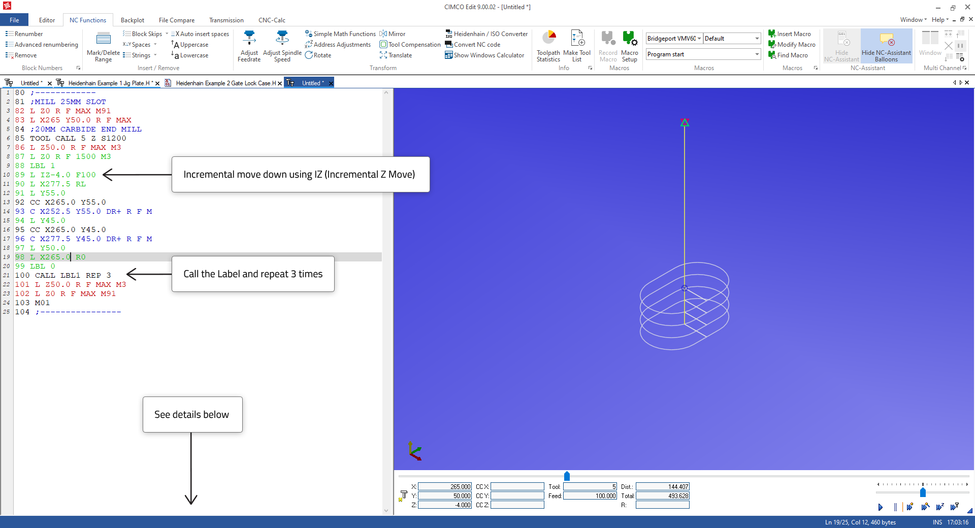
The following technique and cycle will be useful to successfully complete the remaining Heidenhain assignments.
This method of incrementing a given profile or machining move is a simple solution to make several repeated cuts.
|
| Line | Code | Comment |
| 80 | ;------------ | |
| 81 | ;MILL 25MM SLOT | |
| 82 | L Z0 R F MAX M91 | |
| 83 | L X265 Y50.0 R F MAX | Move to centre of Slot |
| 84 | ;20MM CARBIDE END MILL | |
| 85 | TOOL CALL 5 Z S1200 | |
| 86 | L Z50.0 R F MAX M3 | |
| 87 | L Z0 R F 1500 M3 | Move down to Z zero |
| 88 | LBL 1 | Set Label 1 |
| 89 | L IZ-4.0 F100 | Make Incremental Z move down 4 mm, IZ indicates Incremental Move |
| 90 | L X277.5 RL | Slot Profile |
| 91 | L Y55.0 | Slot Profile |
| 92 | CC X265.0 Y55.0 | Slot Profile |
| 93 | C X252.5 Y55.0 DR+ R F M | Slot Profile |
| 94 | L Y45.0 | Slot Profile |
| 95 | CC X265.0 Y45.0 | Slot Profile |
| 96 | C X277.5 Y45.0 DR+ R F M | Slot Profile |
| 97 | L Y50.0 | Slot Profile |
| 98 | L X265.0 R0 | Slot Profile |
| 99 | LBL 0 | Label 1 end |
| 100 | CALL LBL1 REP 3 | Call Label 1 and repeat 3 times, 1 loop plus 3 more x 4mm = 12mm deep. |
| 101 | L Z50.0 R F MAX M3 | |
| 102 | L Z0 R F MAX M91 | |
| 103 | M01 |
There are many convenient cycles to aid programming in the Heidenhain TNC controls. We have used pocket milling in two of the assignments below and we will look at this cycle here.
Please note that the full range of cycles and other program aids in Heidenhain TNC controls are not covered here as the goal is to show how best to create and test programs with CIMCO Edit. The Backplot will interpret and plot most of the cycles. We have used the Rectangular Pocket Cycle 251 which is found in later TNC controls, but Rectangular Pocket Cycle 4 could also be a solution if working with an earlier TNC control.
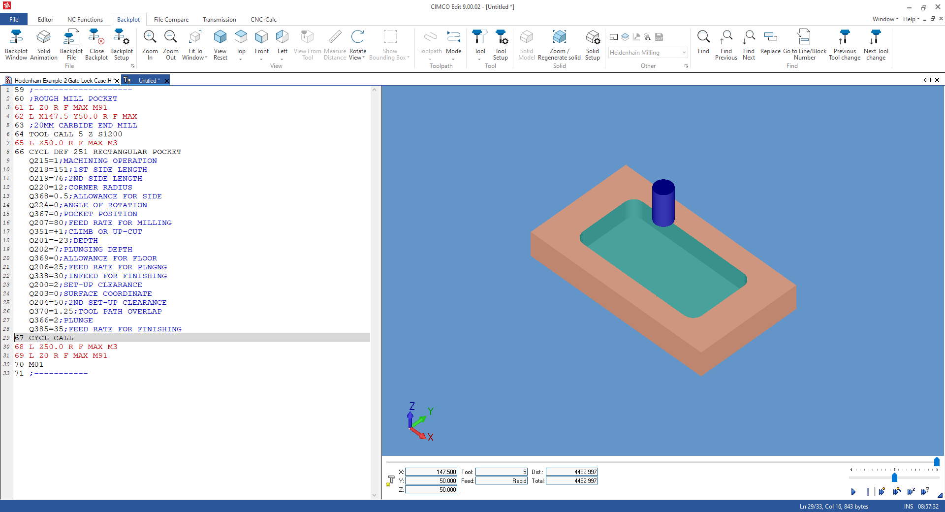 |
Solid Animation provides a better representation of the multi pass machining toolpath generated by this cycle. So, as we did in Assignment 1, the Solid Setup should be configured to create a stock that is slightly bigger than the pocket dimensions and the tool should be set to an 20mm End Mill. This will give a good representation of the pocked milling operation. Let us look at the code below.
| Line | Code | Comment |
| 60 | ;ROUGH MILL POCKET | |
| 61 | L Z0 R F MAX M91 | |
| 62 | L X147.5 Y50.0 R F MAX | Move to the centre of the pocket |
| 63 | ;20MM CARBIDE END MILL | |
| 64 | TOOL CALL 5 Z S1200 | |
| 65 | L Z50.0 R F MAX M3 | Move down to 50 mm above the part |
| 66 | CYCL DEF 251 RECTANGULAR POCKET | Pocket Milling Definition |
| Q215=1;MACHINING OPERATION | Machining operation 1=Roughing 2=Finishing etc. | |
| Q218=151;1ST SIDE LENGTH | As indicated by text | |
| Q219=76;2ND SIDE LENGTH | As indicated by text | |
| Q220=12;CORNER RADIUS | As indicated by text | |
| Q368=0.5;ALLOWANCE FOR SIDE | X & Y Finishing Allowance | |
| Q224=0;ANGLE OF ROTATION | Pocket orientation 3 o/clock = 0 degrees | |
| Q367=0;POCKET POSITION | Position of the tool when the cycle is called 0 = Centre of Pocket | |
| Q207=80;FEED RATE FOR MILLING | As indicated by text | |
| Q351=+1;CLIMB OR UP-CUT | +1 = Climb Milling | |
| Q201=-23;DEPTH | As indicated by text Pocket Depth | |
| Q202=7;PLUNGING DEPTH | As indicated by text cutting Increment down | |
| Q369=0;ALLOWANCE FOR FLOOR | Finishing Allowance in Z at bottom of Pocket | |
| Q206=25;FEED RATE FOR PLNGNG | As indicated by text | |
| Q338=30;INFEED FOR FINISHING | As indicated by text | |
| Q200=2;SET-UP CLEARANCE | Position in Z to start the Cycle | |
| Q203=0;SURFACE COORDINATE | Absolute Z position | |
| Q204=50;2ND SET-UP CLEARANCE | Rapid up to this position between pockets if there are multiples | |
| Q370=1.25;TOOL PATH OVERLAP | How much the tool overlaps = Tool Rad x 1.25 | |
| Q366=2;PLUNGE | Plunging Strategy 0=Vertical, 1=Helical, 2=Zig Zag at angle in Tool Table | |
| Q385=35;FEED RATE FOR FINISHING | As indicated by text | |
| 67 | CYCL CALL | This command will Call the Cycle as does M99 |
| 68 | L Z50.0 R F MAX M3 | |
| 69 | L Z0 R F MAX M91 | |
| 70 | M01 | |
| 71 | ;----------- |