 |
First let us look at a sample program for this simple Drill Jig Plate as below:
|
The program below was created in CIMCO Edit using the NC Assistant macros and general windows editing features. It was refined by testing with the toolpath and later Solid Animation graphics under the Backplot tab in the Editor.
Our goal is to create and test a program in Solid Animation as the one below:
 |
Below you can see a Heidenhain Conversational Dialogue program that will drill the holes and machine the profile contour of the Drill Jig Plate. Each line in the program has a comment associated with it that explains the code. Any lines that do not have an explanation will have been described in a similar earlier block.
It is imperative that the line numbers are sequential and the BEGIN PGM and END PGM have the same program number or name and the same units MM or INCH.
OK, let us look at some Heidenhain Conversational Dialogue code:
| Line | Code | Comment |
| 0 | BEGIN PGM 1234 MM | Program Start, 1234 is the program number but could be text |
| 1 | ;MACHINE DRILL JIG PLATE | The semi-colon ; at the start of the line indicates a comment |
| 2 | ;PROGRAMMER-JOE SMITH | Comment |
| 3 | ;10/05/2021 15:08:09 | Comment |
| 4 | ;--------------- | Comment |
| 5 | ;CENTRE DRILL 11 HOLES | Operation comment |
| 6 | L Z0 R F MAX M91 | Z axis up to top safe position, M91 invokes machine coordinates programming. |
| 7 | ;CENTRE DRILL | Tool comment used by Cimco when creating a Tool List |
| 8 | TOOL CALL 2 Z S800 | Tool Call to activate the Tool with its offsets and set Spindle speed. |
| 9 | L X0.0 Y0.0 R F MAX M03 | Move to position linear at Max Rapid, start spindle forward with M03 |
| 10 | L Z50.0 R F MAX M | Position Z axis |
| 11 | CYCL DEF 200 DRILLING ~ | Drilling Cycle 200 |
| Q200=2.0 ;SET-UP CLEARANCE ~ | Drilling Cycle 200 | |
| Q201=-2.0 ;DEPTH ~ | ||
| Q206=35.0 ;FEED RATE FOR PLUNGING ~ | Drilling Cycle 200 | |
| Q202=-2.0 ;PLUNGING DEPTH ~ | Drilling Cycle 200 | |
| Q210=0.0 ;DWELL TIME AT TOP ~ | Drilling Cycle 200 | |
| Q203=0.5 ;SURFACE COORDINATE ~ | Drilling Cycle 200 | |
| Q204=10.0 ;2ND SET-UP CLEARANCE ~ | Drilling Cycle 200 | |
| Q211=0.5 ;DWELL TIME AT BOTTOM ~ | Drilling Cycle 200 | |
| Q395=0 ;DEPTH REFERENCE | Drilling Cycle 200 | |
| 12 | LBL 1 | Set Label 1 |
| 13 | L X20.0 Y20.0 R F75 M99 | Move to hole 1, M99 will execute the Drill Cycle. |
| 14 | L X40.0 Y20.0 R F M99 | Move to hole 2, etc |
| 15 | L X60.0 Y20.0 R F M99 | |
| 16 | L X80.0 Y20.0 R F M99 | |
| 17 | L X100.0 Y20.0 R F M99 | |
| 18 | L X120.0 Y20.0 R F M99 | |
| 19 | L X140.0 Y20.0 R F M99 | |
| 20 | L X80.0 Y65.0 R F M99 | |
| 21 | L X60.0 Y65.0 R F M99 | |
| 22 | L X40.0 Y65.0 R F M99 | |
| 23 | L X20.0 Y65.0 R F M99 | Move to hole 11, etc |
| 24 | LBL 0 | Set Label End |
| 25 | L Z50 FMAX M05 | Move Z axis up from part. |
| 26 | L Z0 R F MAX M91 | Z axis up to top safe position, M91 invokes machine coordinates programming. |
| 27 | M01 | Option Stop when the switch is set on the CNC control. |
| 28 | ;---------------- | Comment divide between operations, optional. |
| 29 | ;DRILL 11 HOLES 8MM DIA | Header comment for drilling similar to Centre Drill. |
| 30 | L Z0 R F MAX M91 | |
| 31 | ;8MM CARBIDE DRILL | |
| 32 | TOOL CALL 12 Z S4000 | |
| 33 | L X0.0 Y0.0 R F MAX M03 | |
| 34 | L Z50.0 R F MAX M | |
| 35 | CYCL DEF 200 DRILLING ~ | |
| Q200=2.0 ;SET-UP CLEARANCE ~ | ||
| Q201=-20.0 ;DEPTH ~ | ||
| Q206=200.0 ;FEED RATE FOR PLUNGING ~ | ||
| Q202=-5.0 ;PLUNGING DEPTH ~ | ||
| Q210=0.0 ;DWELL TIME AT TOP ~ | ||
| Q203=0.5 ;SURFACE COORDINATE ~ | ||
| Q204=10.0 ;2ND SET-UP CLEARANCE ~ | ||
| Q211=0.0 ;DWELL TIME AT BOTTOM ~ | ||
| Q395=0 ;DEPTH REFERENCE | ||
| 36 | CALL LBL1 | Call Label 1 to retrieve the coordinates from Centre Drilling Section. |
| 37 | L Z50 FMAX M05 | |
| 38 | L Z0 R F MAX M91 | |
| 39 | M01 | |
| 40 | ;--------------- | - |
| 41 | ;MILL PROFILE | |
| 42 | L Z0 R F MAX M91 | |
| 43 | ;20MM CARBIDE END MILL | |
| 44 | TOOL CALL 5 Z S1800 | |
| 45 | L X-25.0 Y42.5 R F MAX M03 | |
| 46 | L Z50.0 R F MAX M | |
| 47 | L Z-18 F1500 | |
| 48 | L X0 RL F200 | Start move to contour RL will activate Radius Compensation. |
| 49 | L Y65 | |
| 50 | CC X20.0 Y65.0 | Absolute Arc Centre. |
| 51 | C X20.0 Y85.0 DR- R | End point position for X, Y. DR- indicates CW direction. |
| 52 | L X90 | |
| 53 | CC X90.0 Y65.0 | |
| 54 | C X110.0 Y65.0 DR- R | |
| 55 | LY55 | |
| 56 | CC X120.0 Y55.0 | |
| 57 | C X120.0 Y45.0 DR+ R | |
| 58 | L X140 | |
| 59 | CC X140.0 Y35.0 | |
| 60 | C X150.0 Y35.0 DR- R | |
| 61 | L Y10 | |
| 62 | CC X140.0 Y10.0 | |
| 63 | C X140.0 Y0.0 DR- R | |
| 64 | L X20 | |
| 65 | CC X20.0 Y20.0 | |
| 66 | C X0.0 Y20.0 DR- R | |
| 67 | L Y42.5 | |
| 68 | L X-25 R0 | R0 de-activates Radius compensation. |
| 69 | L Z50 FMAX | |
| 70 | L Z0 R F MAX M91 | Z axis up to top safe position, M91 invokes machine coordinates programming. |
| 71 | M09 | Stop Coolant |
| 72 | M05 | Stop Spindle |
| 73 | L Z0 R F MAX M91 | |
| 74 | M30 | End of Program M code |
| 75 | END PGM 1234 MM | Program End, 1234 is the program number but could be text must be the same as the Start. |
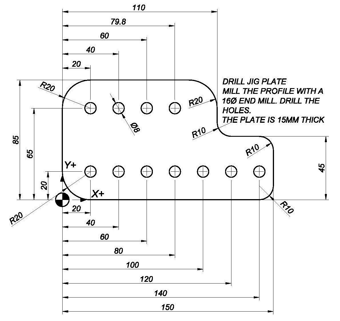
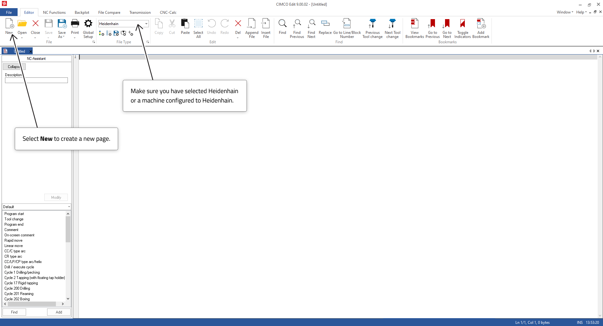
Now that we've had a look at the program code, we will consider how this was created in the CIMCO Edit. You might want to print the Drill Jig Plate for reference when we are constructing the program.
 |
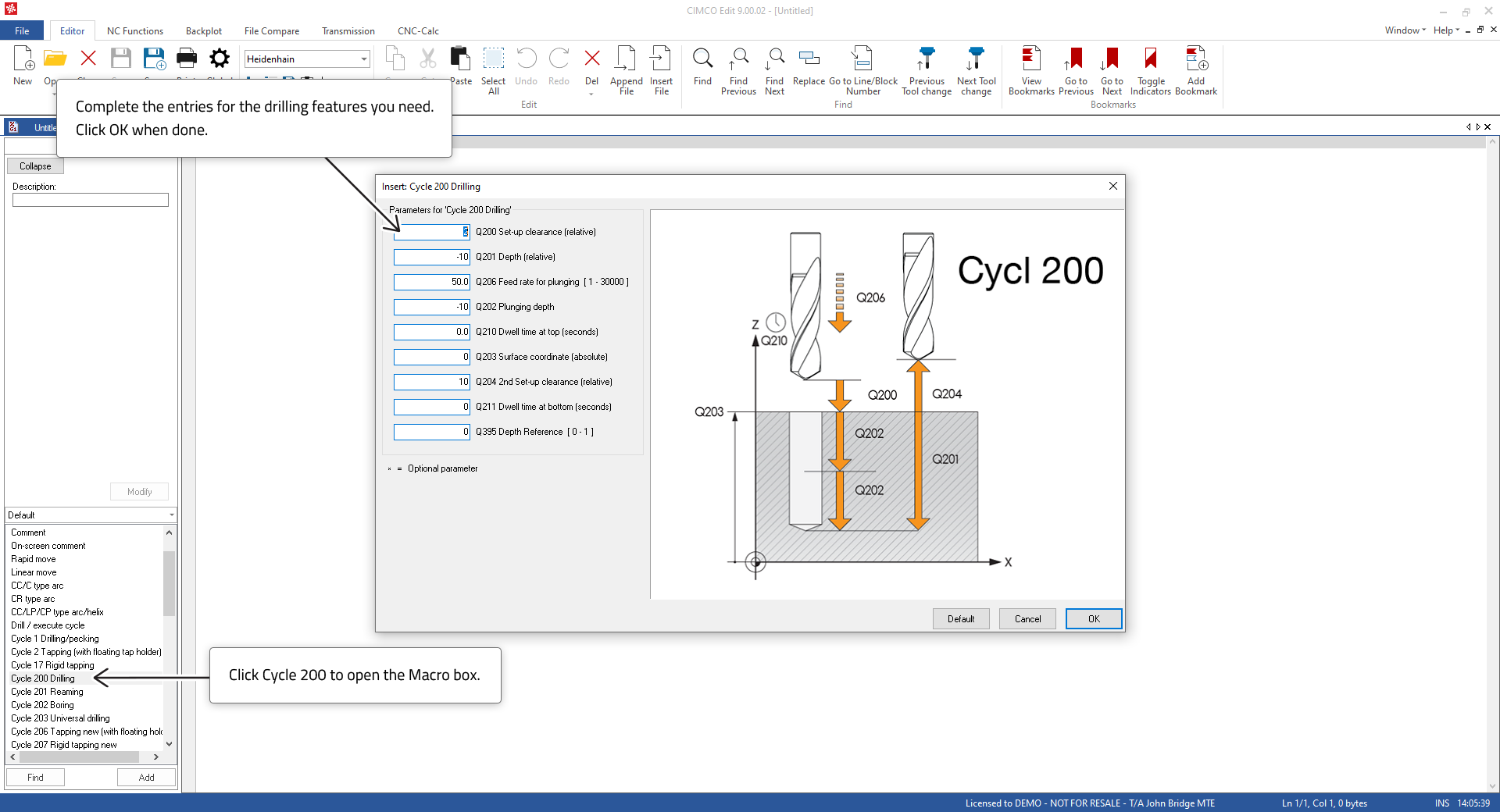
Let us start by center drilling the holes with a Drill Cycle. We will use Cycle 200 as it has more features than Drilling Cycle 1.
 |
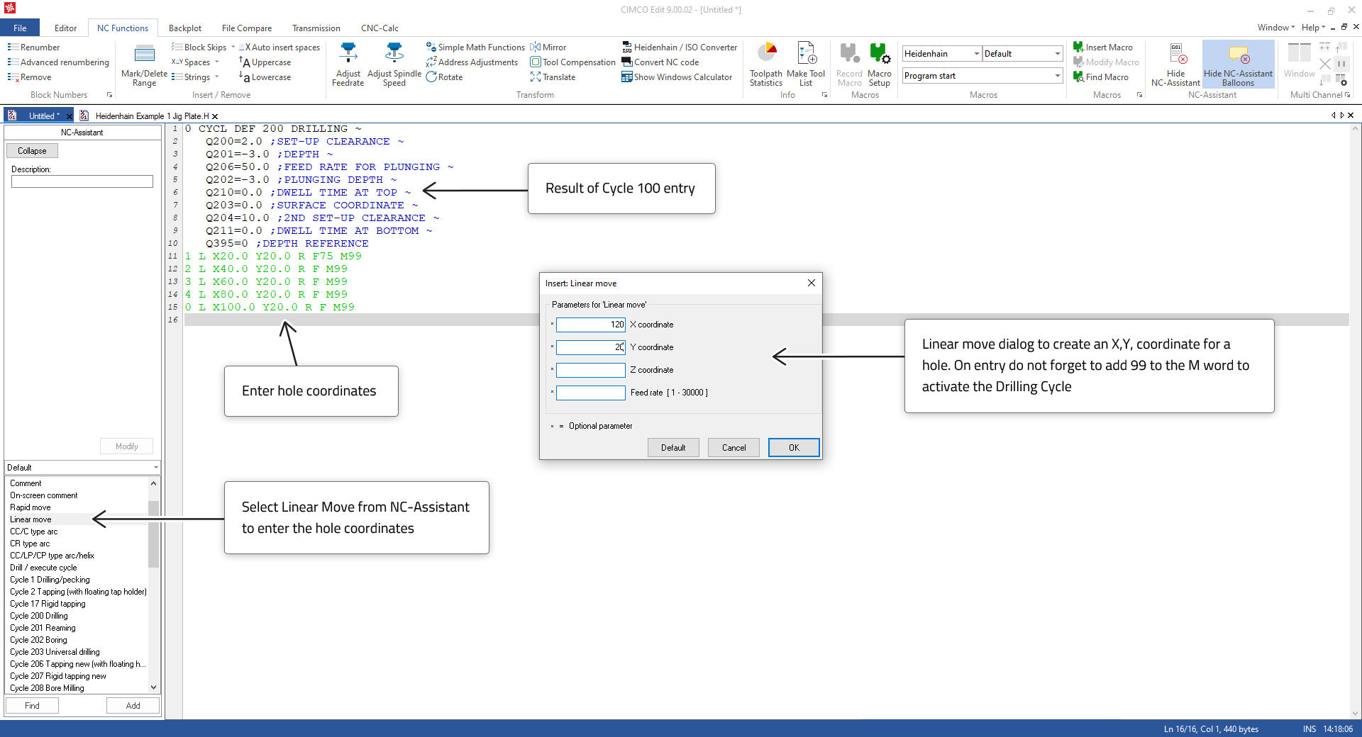 |
When you have completed entering the hole coordinates test it with the Backplot.
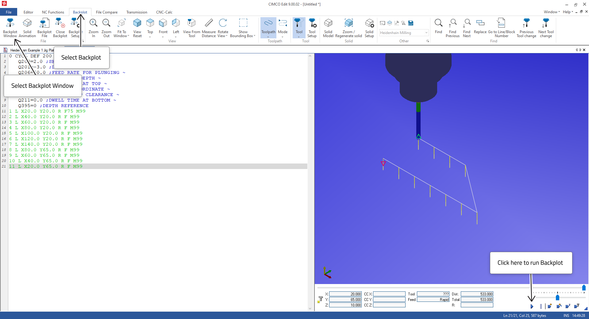 |
If it doesn’t look like the image above, then debug the entries until it does.
When you have the center drilling working, you can add the 8mm hole drilling by copy/pasting the lines as seen in the image below. We will need to use the hole coordinates again for the drilling so we can use a Label to recall the set of hole coordiantes for the 8mm drilling operations on the holes.
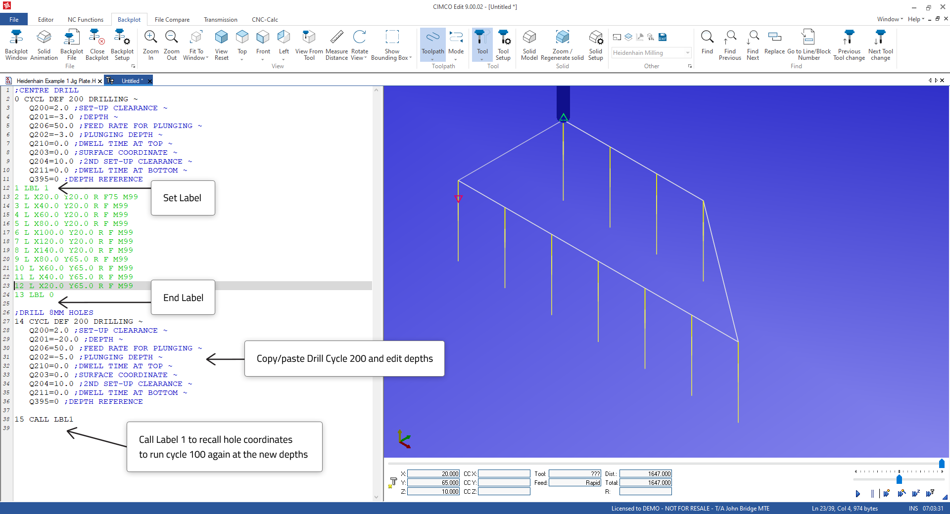 |
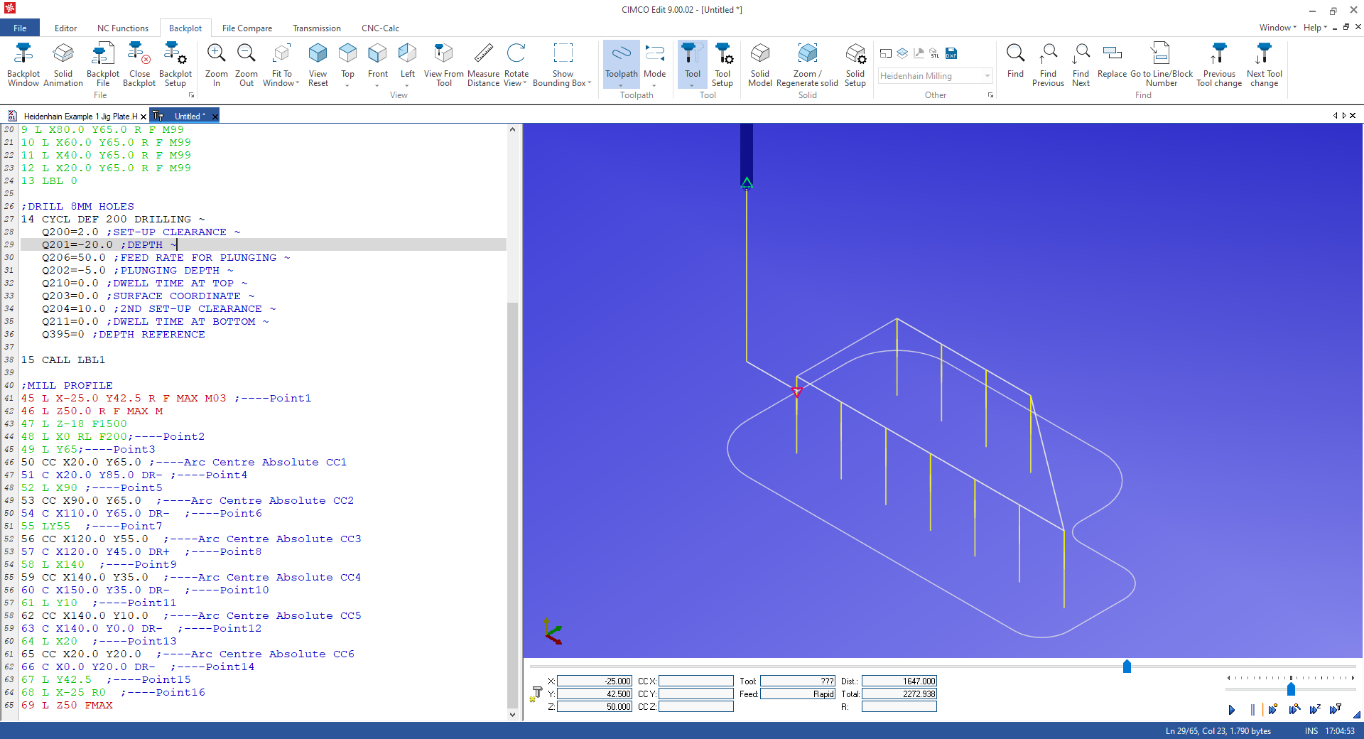
When your entries are correct, you will see the drilling of the deeper holes in the Backplot.
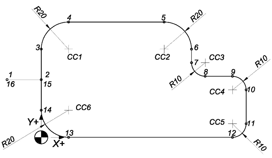
Next we will create the profile starting from a position outside the profile at X-25.0, Y42.2 (1) and moving onto the profile and around in a clockwise direction. The profile will be generated by linear and circular moves using NC-Assistant. The points in the diagram below indicate the sequence of moves.
 |
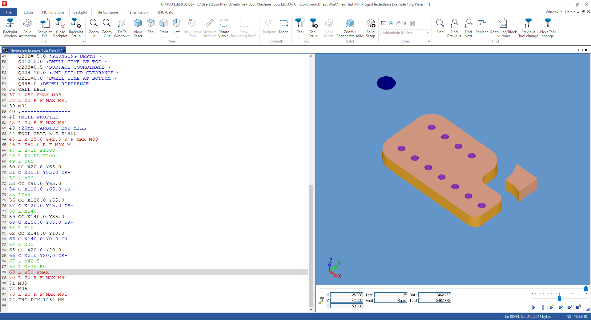
When you have the profile correct, it will look as in the image below.
 |
The program lines below correspond to the points in the drawing above.
| Line | Code | Comment |
| ;MILL PROFILE | ||
| 45 | L X-25.0 Y42.5 R F MAX M03 | Point 1, Start Spindle M03 |
| 46 | L Z50.0 R F MAX M | Note that the L at the start of the line indicated a linear move |
| 47 | L Z-18.0 F1500 | |
| 48 | L X0 RL F200 | Point 2 |
| 49 | L Y65.0 | Point 3 |
| 50 | CC X20.0 Y65.0 | Arc Centre CC1 – Note CC at the start of the line indicates Circle Centre |
| 51 | C X20.0 Y85.0 DR- | Point 4 – Note C at the start of the line indicates Circular move, DR- Direction CW |
| 52 | L X90.0 | Point 5 |
| 53 | CC X90.0 Y65.0 | Arc Centre CC2 |
| 54 | C X110.0 Y65.0 DR- | Point 6 |
| 55 | LY55.0 | Point 7 |
| 56 | CC X120.0 Y55.0 | Arc Centre CC3 |
| 57 | C X120.0 Y45.0 DR+ | Point 8, Note DR+ change of Arc direction CCW |
| 58 | L X140.0 | Point 9 |
| 59 | CC X140.0 Y35.0 | Arc Centre CC4 |
| 60 | C X150.0 Y35.0 DR- | Point 10 |
| 61 | L Y10.0 | Point 11 |
| 62 | CC X140.0 Y10.0 | Arc Centre CC5 |
| 63 | C X140.0 Y0.0 DR- | Point 12 |
| 64 | L X20.0 | Point 13 |
| 65 | CC X20.0 Y20.0 | Arc Centre CC6 |
| 66 | C X0.0 Y20.0 DR- | Point 14 |
| 67 | L Y42.5 | Point 15 |
| 68 | L X-25.0 R0 | Point 16 |
| 69 | L Z50 FMAX |
When we are dealing with arcs at 90 degrees the end points and arc centers are easy to calculate. It's simply a matter of reading the drawing or doing some simple summation. When we are dealing with arcs between lines, that are not at 90 degrees, then we can use a program such as CIMCO CNC-Calc (add-on for CIMCO Edit) to generate the toolpath or do trigonometry calculations as the end points and arc centers are not so easily calculated.
Now that we have created toolpaths to complete the machining and tested their validity, we can complete the program with the other information required to control the Z axis, Spindle, etc. It is an important principle that each tool should be programmed as a small self-contained program so that any tool section in the program can be executed independently if required.
So, each tool section should have a Header, Machining, and End section.
| HEADER | ||
| 41 | ;MILL PROFILE | Comment indicating the operation with the Tool in this section (Optional but advisable) |
| 42 | L Z0 R F MAX M91 | -Z axis up to top safe position, M91 invokes machine coordinates programming. |
| 43 | ;20MM CARBIDE END MILL | Tool Description used by CIMCO to create a Tool List (Optional but advisable) |
| 44 | TOOL CALL 5 Z S1800 | The Tool and the offset will be activated for Length and Dia. Speed set. |
| END SECTION | ||
| 25 | L Z50 FMAX M05 | Move Z axis up from part. Stop the Spindle |
| 26 | L Z0 R F MAX M91 | Z axis up to top safe position, M91 invokes machine coordinates programming. |
| 27 | M01 | Option Stop when switch is set on the CNC control, used when checking is required. |
When the program is completed, we can test it using Solid Animation to get a better visualization of how the finished part will look. To do this, there’s some setting up to do first.
Before machining, we need to adjust the size to the initial stock using the Solid Setup dialog. By default, Solid Setup will scan the program to get the min/max material sizes. You may, however, want to enter the actual stock sizes to get a better representation.
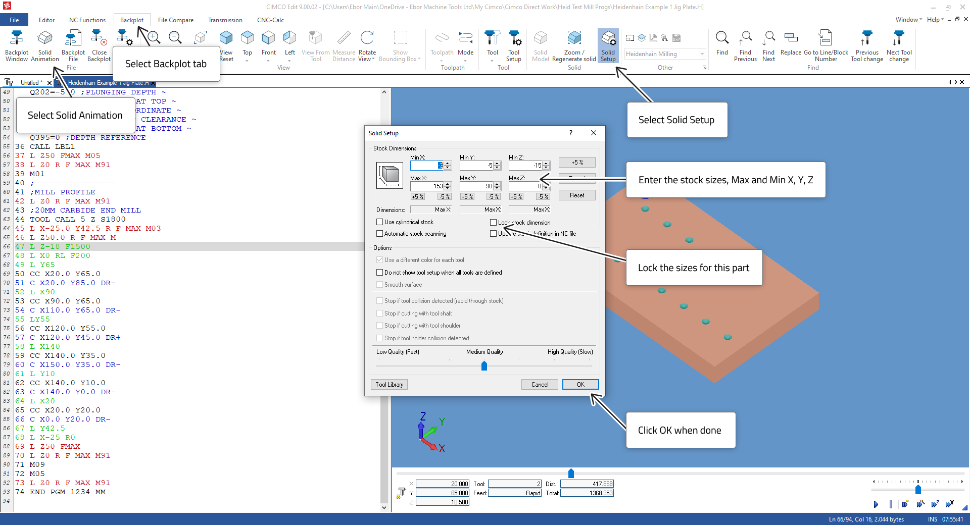 |
For this part we recommend the following Solid Setup values:
X Min = -3
X Max = 153
Y Min = -3
X Max = 88
Z Min = -15
Z Max = 0
We suggest selecting the Lock Stock Dimensions while testing the part to stop the automatic scanning. If you want to use the Solid Animation test more than once.
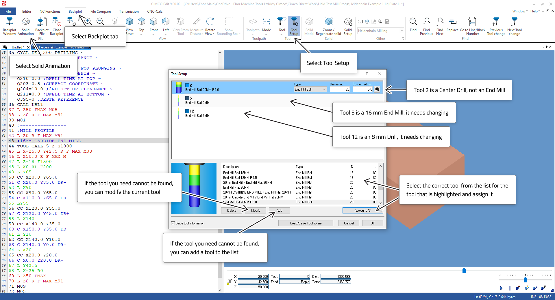
We also need to go to Tool Setup and adjust the tool list to match the tools being used to machine the part.
 |
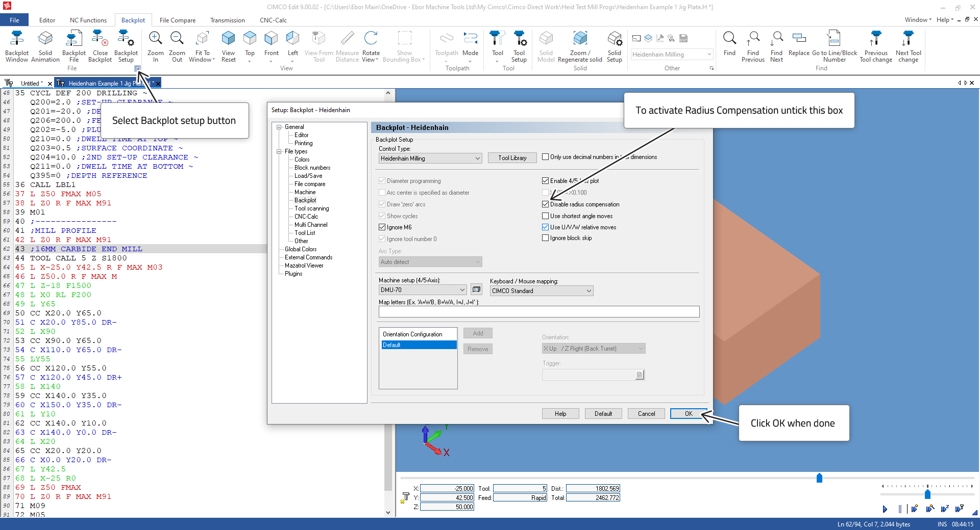
If we are using Radius Compensation, we must activate this feature.
 |
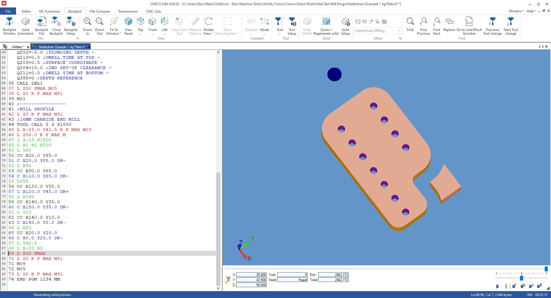
The final result should look like the image below. The part can be rotated by holding down the left mouse-button and dragging.
A little more programming is needed to clear away the corner before profiling. The programming principles needed to do so have all been demonstrated above.
 |