|
Only milling tools are supported. |
This section describes the Advanced Tool scan feature in CIMCO Edit v7. All commands are case insensitive, but the values are kept in all caps for compatibility reasons.
The Advanced Tool scanning feature allows you to automatically scan tool dimensions from the NC program file. With this function, the tool number, type, and dimensions will be automatically read from the NC program.
|
Only milling tools are supported. |
When using Automatic Tool scanning, the tool scanner searches for lines in the NC file that contain the tool line trigger. The default trigger keyword is TOOL, and if necessary the user can change the tool line trigger.
The tool line is expected to be inside comments, and it uses the Comment end character from the machine settings if available.
When the tool is scanned, the order of the dimension keywords is irrelevant. The user is able to change the keywords.
|
Some words can significantly slow down the performance if they occur often in the NC file. |
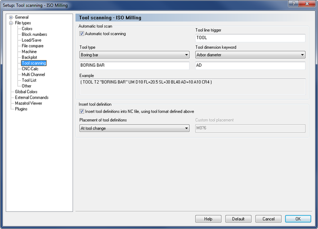
The Tool Scanning configuration dialog is shown below:
 |
|
Tool scanning setup window. |
Check this field to automatically scan tool dimensions from the NC program.
Enter in this field the word used as tool scanning trigger. Only normal characters A-Z and a-z are accepted. The default word is TOOL.
Use this field to select the type of tool used for the operation. In the field below, you can edit the name of the tool, and the changes will automatically appear in the Example field. All characters are supported.
Use this field to select the keyword that should correlate to a tool dimension value. In the field below, you can edit the keyword of the selected tool dimension, and the changes will automatically appear in the Example field. Only normal characters A-Z and a-z are supported.
This field shows an example of the selected tool with all its parameters.
|
The fields "Tool Trigger", "Tool Type" and "Tool dimension Keyword" are only used to insert synonyms for standard keywords in the configuration. It is recommended to use the default keywords, as a change may cause problems. |
Check this option to enable to insertion of tool definitions into NC file, using the tool format defined above. The insertion is done after Tool Setup.
Use this field to select where the tool definitions should be placed in the file. You can select Top of file, At tool change or Custom from the drop-down list. If the selected placement fails, the tool definition is placed at line 1.
Use this field to specify a keyword or regular expression (Perl) to search for the line, the tool definition should be placed after. If the search fails, the tool definition is placed at line 1.
The custom tool placement can be specified in two ways:
Simple: In the simple mode you use a keyword such as M6, G2 to specify the tool placement. Then all the tools are placed after the first occurrence of M6 or G2.
Advanced: The advanced mode lets you use a regular expression (Perl) to specify the tool placement.
Examples:
M0?6 which matches M6 or M06
M0+6 which matches M06 or M006, but not M6.
You can use the following wildcards and repetition characters to specify the advanced custom tool placement.
| ˆ | Beginning of line or string |
| $ | End of line or string |
| . | Any character except newline |
| * | Match previous character 0 or more times |
| + | Match previous character 1 or more times |
| ? | Match previous character 0 or 1 time |
| | | Alternative, either....or |
| ( ) | Grouping |
| [ ] | Set of characters |
| { } | Repetition modifier |
| \ | Quote or special |
| {n} | Match previous character exactly n times |
| {n,} | Match previous character at least n times |
| {n,m} | Match previous character at least n but not more than m times |
Please refer to Perl regular expression documentation for more information.
|
This field is only activated if Custom is selected in the Placement of tool definitions field. |
|
All tool lines can be grouped at the start of the program. In ISO codes, the tool lines are expected to be inside comments i.e. between parentheses. For Heidenhain programs, tool lines start with a semicolon. |
Tool lines start with the trigger word TOOL followed by the tool number, and the tool type in inverted commas.
The default tool types are named as follows:
| End mill flat: | "END MILL FLAT" |
| End mill sphere: | "END MILL SPHERE" |
| End mill bull: | "END MILL BULL" |
| Taper mill: | "TAPER MILL" |
| Drill: | "DRILL" |
| Center drill: | "CENTER DRILL" |
| Spot drill: | "SPOT DRILL" |
| Reamer: | "REAMER" |
| Boring bar: | "BORING BAR" |
| Counter bore: | "COUNTER BORE" |
| Counter sink: | "COUNTER SINK" |
| Chamfer mill: | "CHAMFER MILL" |
| Face mill: | "FACE MILL" |
| Slot mill: | "SLOT MILL" |
| Rad mill: | "RAD MILL" |
|
If a tool line contains an unknown tool type, End mill flat is used. |
The tool type is then followed by dimension keywords and values. The default keywords are:
| D = Diameter: | Integer, decimal or fraction. |
| CR = Corner Radius: | Integer, decimal or fraction. |
| A = Taper Angle: | Integer, decimal or fraction. |
| FL = Flute Length: | Integer, decimal or fraction. |
| SL = Shaft Length: | Integer, decimal or fraction. |
| BL = Body Length: | Integer, decimal or fraction. |
| AD = Arbor Diameter: | Integer, decimal or fraction. |
|
You can define tools in the NC programs with and without '=' between the dimension keyword and value. |
You can change between metric and imperial tools by adding UM for Metric (mm) and UI for Imperial (inch).
ISO comments
(TOOL1 "FACE MILL" UM D=42 CR=0.8 FL=6.25 SL=30 BL=50 AD=12.5)
(TOOL3 "DRILL" FL36.1234 SL=0 BL = 36 AD6 A120 UM D6 CR0)
Heidenhain comment
; TOOL12 "TAPER MILL" A=12.345 D=8 AD=21.13 CR=0 FL=20 SL=30 BL=50 UM
Imperial tool
(TOOL136 "END MILL FLAT" UI D=1/8 CR=0 FL=1 SL=2 BL=3 AD=1/8)
|
If a dimension keyword is missing, the value of that keyword is taken from the default tool. Remember to insert space between parameter definitions. |