|
The Transform menu. |
This section describes the functions under the menu Transform, which allows you to quickly write and change NC programs.
|
The Transform menu. |
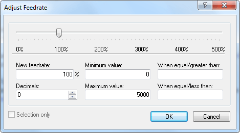
In this dialog, it is possible to adjust the feedrate of the active program. To do this, click and drag the pointer or click on the sliding bar of the pointer, or enter the new feedrate in the field New feedrate (see the following in this section). Click OK to apply the command or Cancel to close the window without any changes taking effect.
 |
|
Adjust feedrate dialog. |
Enter into this field, the percentage with which the feedrate should be changed.
Enter the minimum feedrate into this field (in mm/min).
Enter the maximum feedrate into this field (in mm/min).
Enter the number of decimals to the right of the decimal point into this field.
Only values greater than or equal to the value specified here will be modified.
Only values less than or equal to the value specified here will be modified.
Check this field to change the feedrate in the selected program blocks only.
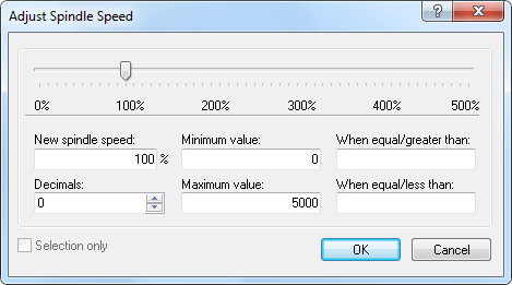
In this dialog, the spindle speed of the active program is adjusted. To do this, click and drag the pointer or click on the sliding bar of the pointer, or enter the new spindle speed in the field New spindle speed (see the following in this section). Click OK to apply the command or Cancel to close the window without any changes taking effect.
 |
|
Adjust spindle speed dialog. |
Enter into this field, the percentage with which the spindle speed should be changed.
Enter the minimum spindle speed here (in rev/min).
Enter the maximum spindle speed here (in rev/min).
Enter the number of decimals to the right of the decimal point here.
Only values greater than or equal to the value specified here will be modified.
Only values less than or equal to the value specified here will be modified.
Check this field to change the spindle speed in the selected program blocks only.
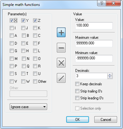
Performs simple mathematical functions on the chosen NC file parameters.
 |
|
Simple math functions dialog. |
Check the fields of the parameters to be changed.
Check this option to enter parameters with more than one character. This enables an input field where special characters (Ó, Ö, Ø...) or multi-digit (ABC) parameter names can be entered.
Use this field to specify UPPER and/or lower case of the parameters to be changed.
Adds the specified value to all selected parameters.
Subtracts the specified value from all selected parameters.
Multiplies all selected parameters by the specified value.
Divides all selected parameters by the specified value.
Use this field to enter the value that will be inserted in the mathematical function (Addition / Subtraction / Multiplication / Division).
Enter the maximum value in this field. Parameters with values higher than specified here after performing the mathematical function will be set to this maximum value.
Enter the minimum value in this field. Parameters with values lower than specified here after performing the mathematical function will be set to this minimum value.
In this field, enter the number of decimals to the right of the decimal point.
Check this field to provide the new value with the same number of decimals as the original value.
Check this field to remove all zeros from the end of the number.
Check this field to remove all zeros from the beginning of the number.
Check this field to change the value of the selected program blocks only.
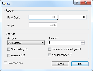
In this dialog you can rotate the outline around a specified point and with a specified angle. Click OK to apply the command or Cancel to close the window without any changes taking effect.
 |
|
Rotate dialog. |
Enter the coordinates of the center of the rotation in these fields.
Enter the angle of rotation by degrees in this field.
Here you can specify the arc type by selecting one of the four different types:
Enter into this field the number of decimals to the right of the decimal point.
Check this field to remove all zeros from the end of the number.
Check this field when the control is preset for relative coordinates (G91).
Check this field to use comma as decimal separator.
Check this field to use non-modal X/Y/Z values.
Check this field to rotate the selected program blocks only.
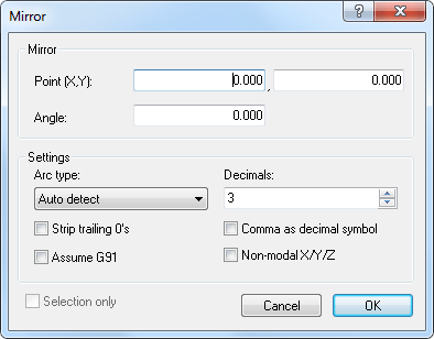
In this dialog you can mirror the outline around a specified line. Click OK to apply the command or Cancel to close the window without any changes taking effect.
 |
|
Mirror dialog. |
Enter into these fields the coordinates of the point of the mirror axis.
Enter into this field the angle of rotation by degrees of the mirror axis.
Here you can specify the arc type by selecting one of the four different types:
Enter into this field the number of decimals to the right of the decimal point.
Check this field to remove all zeros from the end of the number.
Check this field when the control is preset for relative coordinates (G91).
Check this field to use comma as decimal separator.
Check this field to use non-modal X/Y/Z values.
Check this field to mirror the selected program blocks only.
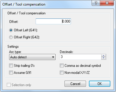
In this dialog you can define a toolpath compensation (offset) for the active program, from the programmed workpiece contour to the left (G41), or to the right (G42) - based on the direction of feed -, in order to compensate different tool sizes.
 |
|
Offset/Tool compensation dialog. |
Enter the offset value into this field.
Enable compensation of the milling path, offset left (G41).
Enable compensation of the milling path, offset right (G42).
Here you can specify the arc type by selecting one of the four different types:
Enter into this field the number of decimals to the right of the decimal point.
Check this field to remove all zeros from the end of the number.
Check this field when the control is preset for relative coordinates (G91).
Check this field to use comma as decimal separator.
Check this field to use non-modal X/Y/Z values.
Check this field to offset the selected program blocks only.
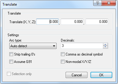
This dialog translates the outline. The outline is moved to a position offset by the values entered in the Translate (X,Y,Z) fields.
 |
|
Translate dialog. |
Enter into these fields the X, Y, and Z values to offset the outline.
Here you can specify the arc type by selecting one of the four different types:
Enter into this field the number of decimals to the right of the decimal point.
Check this field to remove all zeros from the end of the number.
Check this field when the control is preset for relative coordinates (G91).
Check this field to use comma as decimal separator.
Check this field to use non-modal X/Y/Z values.
Check this field to translate the selected program blocks only.
Use this function to convert Heidenhain CNC Programs to ISO Programs.
Opens Windows calculator.