|
The Solid Model is only available for Milling operations. |
In this section, the Backplot function Solid and the simulation of the Solid Model are described.
|
The Solid Model is only available for Milling operations. |
 |
|
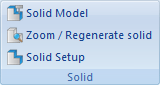
The Solid menu. |
Shows / Hides the solid model.
Click on this icon to toggle between the toolpath view and the Solid visualization with toolpath.
Creates a solid from the current view.
Click this icon to generate a solid model of the workpiece with toolpath.
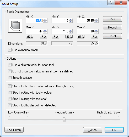
Click on this icon to configure the Solid Model. The specified stock dimensions are the minimum and maximum X, Y, Z values in your NC program. If you want to increase or decrease the stock dimensions to get a much more even toolpath, then click one or several times the corresponding button (+5% or -5%) to obtain the desired dimensions. Use the button Round to round off stock dimensions.
 |
|
Solid Setup dialog. |