|
Global setup scanning window. |
Scanning is a feature that can be accessed through the Global Setup. Scanning enables the workpiece, fixture, work offset, tools and holders to be automatically loaded upon starting Backplot / Machine Simulation. Scanning can be accessed by locating, Program Tabs - Editor - Global Setup - Machine Configuration - Scanning.
|
Global setup scanning window. |
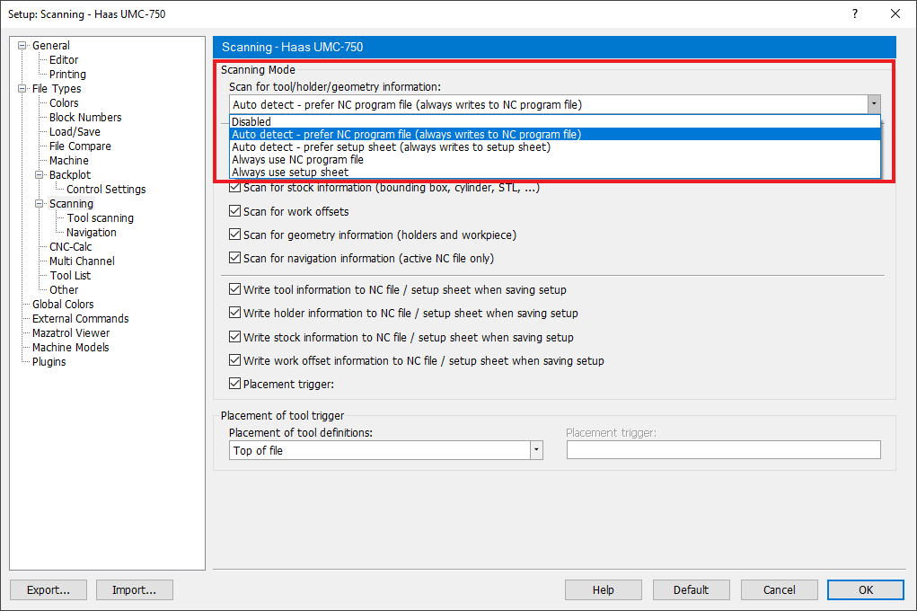
The Scanning window has three sections, Scanning Mode, Read/Write Settings and NC File Placement Settings.
Scanning Mode has three options.
 |
|
Scanning Mode |
Reads the scanning commands that are currently in the nc file.
Scan setup file reads an external file which contains the same scanning commands that would be located within the nc file, but using default settings so that it is neutral to all controls. The setup file should be located in the same location as the nc file and have the same name, but the .setup extension.
|
Setup file. |
No scanning is done.
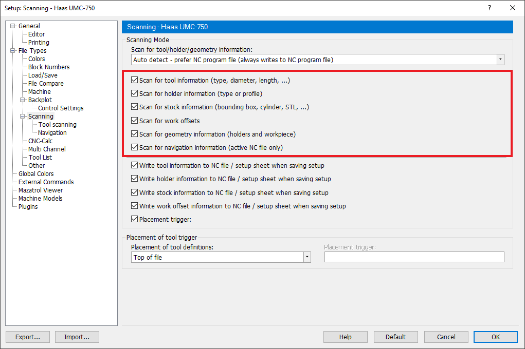
There are three columns within this section, Definition, Read and Write.
 |
|
Scanning read options |
Contains the objects that can be scanned, Geometries, Holders, Navigation, Stock, Tools, Work offset.
Check boxes correspond with each definition. Check the box beside the definition to automatically read its description from the nc or setup file.
 |
|
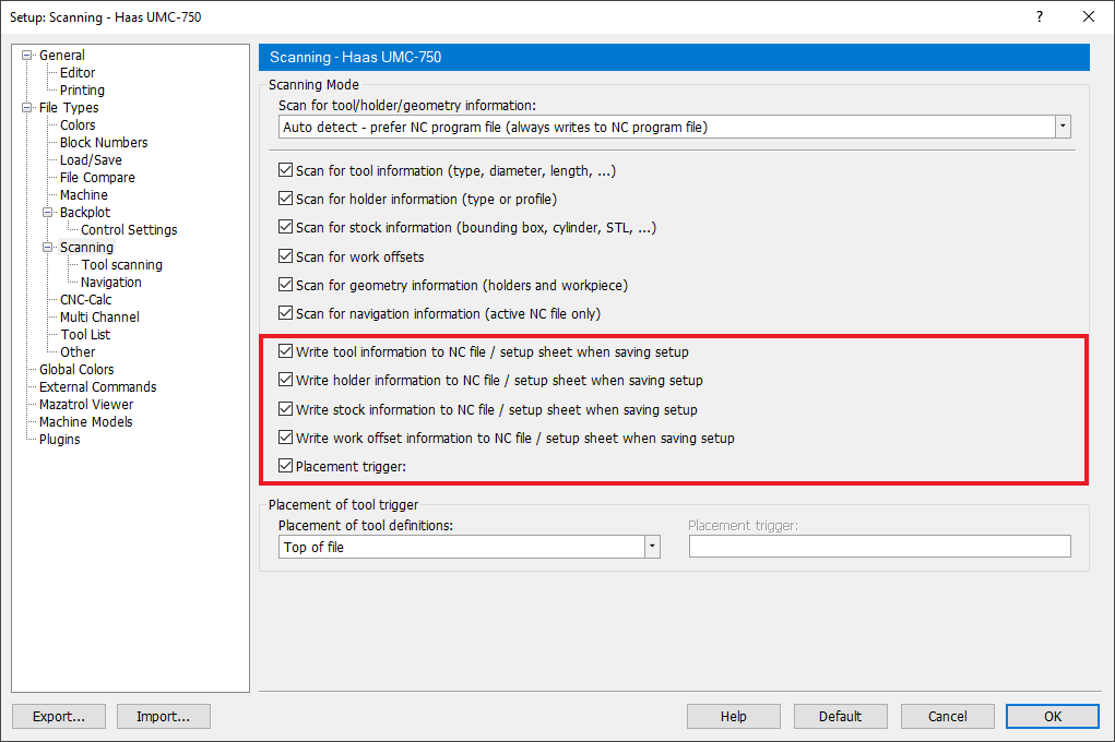
Scanning write options |
Check boxes correspond with each definition. Check the box beside the definition to automatically write the description into the nc or setup file.
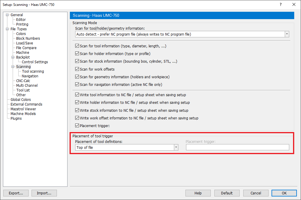
NC File Placement Settings mode has three sections,
 |
|
NC File Placement Settings. |
Contains the objects that are scanned, by clicking on each of the definitions it allows its placement to be selected.
Allows the end user to choose the placement of the scanning commands from default options. Use this field to select where the tool definitions should be placed in the file. You can select Top of file, At tool change or Custom from the drop-down list. If the selected placement fails, the tool definition is placed at line 1.
|
Placement options. |
Allows the end user to choose the placement of the scanning commands. Use this field to specify a keyword or regular expression (Perl) to search for the line, the tool definition should be placed after. If the search fails, the tool definition is placed at line 1.
The custom tool placement can be specified in two ways:
Simple: In the simple mode you use a keyword such as M6, G2 to specify the tool placement. Then all the tools are placed after the first occurrence of M6 or G2.
Advanced: The advanced mode lets you use a regular expression (Perl) to specify the tool placement.
Examples:
M0?6 which matches M6 or M06
M0+6 which matches M06 or M006, but not M6.
You can use the following wildcards and repetition characters to specify the advanced custom tool placement.
| ˆ | Beginning of line or string |
| $ | End of line or string |
| . | Any character except newline |
| * | Match previous character 0 or more times |
| + | Match previous character 1 or more times |
| ? | Match previous character 0 or 1 time |
| | | Alternative, either....or |
| ( ) | Grouping |
| [ ] | Set of characters |
| { } | Repetition modifier |
| \ | Quote or special |
| {n} | Match previous character exactly n times |
| {n,} | Match previous character at least n times |
| {n,m} | Match previous character at least n but not more than m times |
Please refer to Perl regular expression documentation for more information.
|
This field is only activated if Custom is selected in the Placement of tool definitions field. |
Sample below shows scanning commands in a Setup file.
TOOL 1 "BORING BAR" HOLDER=H1 UM D10 FL=20.5 SL=30 BL40 AD=10 A10 CR4
TOOL 2 "END MILL SPHERE" HOLDER=H1 UM D10 FL=20.5 SL=30 BL40 AD=10 A10 CR4
HOLDER BEGIN H1 "BT50" 69.85, 69.85, 3
100, 100, 12.5 100, 85, 4.33
85, 85, 6.34 85, 100, 4.33
100, 100, 7.3
HOLDER END
WORKPIECE ID1 "workpiece_1.stl" X0 Y0 Z0 A0 B0 C0
WORKPIECE ID2 "workpiece_2.stl" X0 Y0 Z0 A0 B0 C0
FIXTURE ID1 "fixture_1.stl" X0 Y0 Z0 A0 B0 C0
FIXTURE ID2 "fixture_2.stl" X0 Y0 Z0 A0 B0 C0
WCS ID0 X100 Y100 Z0
WCS ID1 X300 Y200 Z0
WCS ID2 X300 Y300 Z0
Sample below shows how to load .stl model as fixture or workpiece.
TYPE ID(ID) "FILENAME" X(NUMBER) Y(NUMBER) Z(NUMBER) A(NUMBER) B(NUMBER) C(NUMBER)
TYPE : Either of the two strings: WORKPIECE /FIXTURE
(ID) : Integer
(FILENAME) : String with an ".stl" extension
(NUMBER) : Integer, Float : X,Y,Z Coordinate : A,B,C Euler transformation
WORKPIECE ID1 "workpiece_1.stl" X0 Y0 Z0 A0 B0 C0
WORKPIECE ID2 "workpiece_2.stl" X0 Y0 Z0 A0 B0 C0
FIXTURE ID1 "fixture_1.stl" X0 Y0 Z0 A0 B0 C0
FIXTURE ID2 "fixture_2.stl" X0 Y0 Z0 A0 B0 C0
FIXTURE ID3 "fixture_2.stl" X0 Y0 Z0 A0 B0 C0
Sample below shows how to load a tool.
TOOL (TOOL NUMBER) "TYPE" (UNIT) (DIMENSIONS)
Sample below shows how to load a tool with a holder.
TOOL (TOOL NUMBER) "TYPE" HOLDER=(HOLDER ID) (UNIT) (DIMENSIONS)
TOOL NUMBER : Integer with tool number, at the moment supports characters `a-z` as well.
TYPE : String with tool type
HOLDER ID : Optional, Alphanumeric string [a-zA-Z0-9_-]
UNIT : Optional parameter with two possible values: :UM = Metric :UI = Imperial
DIMENSIONS : List of tool dimensions, described below.
|
Refer to the Tool Scanning page for information on Automatic Tool Scanning. |
Sample below shows how to load a holder.
HOLDER BEGIN (ID) "NAME" (UNIT)
(NUMBER), (NUMBER), (NUMBER) # Holder Segment: (Upper diameter, Lower diameter, Length of the segment)
(NUMBER), (NUMBER), (NUMBER) # One holder segment per line
(NUMBER), (NUMBER), (NUMBER)
HOLDER END
ID : alphanumeric string [a-zA-Z0-9_-]
NAME : alphanumeric string [a-zA-Z0-9_-], must be encapsulated with double quotation marks
UNIT : Optional parameter with two possible values: :UM = Metric :UI = Imperial
NUMBER : Integer, Float, Fraction
HOLDER BEGIN H2 "B2C4-0011"
42.9514,1.524,45.9994
45.9994,6.0706,45.9994
45.9994,2.00406,39.0652
37.9984,4.0132,37.9984
39.06012,2.00406,45.9994
45.9994,3.1242,45.9994
45.9994,1.27,43.4594
22.225,3.175,15.875
15.875,31.75,15.875
15.875,1.4478,12.7
12.7,5.334,12.7
14.986,0.508,16.002
16.002,11.43,16.002
16.002,0.508,14.986
HOLDER END
Sample below shows how to load the work offset.
WCS ID(INDEX) X(NUMBER) Y(NUMBER) Z(NUMBER)
INDEX : Integer referring to the work offset index. (Currently we support 7 different work offsets (0-6))
NUMBER : Integer, Float
: X,Y,Z Coordinate
WCS ID0 X100 Y100 Z0
WCS ID1 X300 Y200 Z0
WCS ID2 X300 Y300 Z0