 |
|
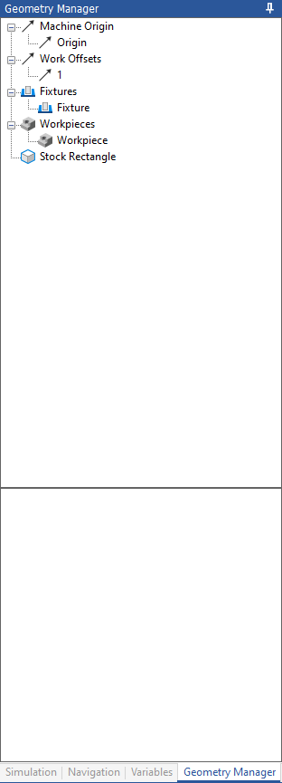
Geometry Manager tab. |
This section describes the Geometry Manager tab from the docking tab pane. The Geometry Manager is used for adding a workpiece, fixture, and machine models. The Geometry Manager contains the following elements as described below.
|
|
Geometry Manager tab. |
Specify a position on the machine relative to the machine zero position using the translation properties below.
Adjust work offsets using the translation properties below.
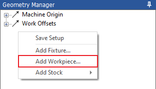
Shows the workpieces that have been added to the backplot environment. To add a workpiece, right-click in the Geometry Manager and select Add Workpiece. Locate the file and click Open to add. The workpiece will appear below Workpiece.
 |
|
Adding a workpiece. |
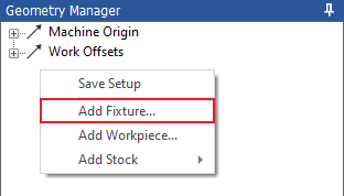
Shows the fixtures that have been added to the backplot environment. To add a fixture, right-click in the Geometry Manager and select Add Fixture. Locate the corresponding STL file and click Open to add. The fixture will appear below Fixture.
 |
|
Adding a fixture. |
Stock Shows the stocks that have been added to the backplot environment. To add stock, right-click in the Geometry Manager and select Add Stock. Either add the stock as an STL file or manually define the stock as a box or cylinder. The stock will appear below Stock.
 |
|
Adding a Stock. |
Once a fixture, workpiece and stock has been added they will appear below their corresponding header.
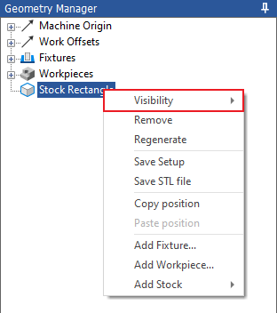
Right click on the workpiece, fixture or stock in the geometry manager and select Toggle Visibility to toggle between viewing the component as visible, transparent, or hidden.
 |
|
Toggling the visibility. |
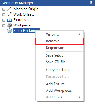
Remove a component from the Backplot window and Geometry Manager.
 |
|
Removing a component. |
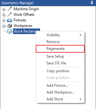
Regenerate the stock relative to the position in the NC program.
 |
|
Regenerating the stock. |
Right click in the geometry manager and select Save Setup to save the machine setup. Any changes that have been made to the added fixture and/or workpiece will be saved for when the NC code and machine is reopened.
 |
|
Saving the setup of a machine. |
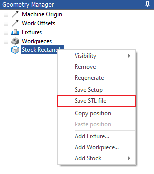
Right click on the stock in the Geometry Manager and select Save STL file to save the stock at its current progress as an STL.
 |
|
Saving the stock as an STL. |
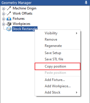
Copy the position of a component.
Paste the position of a component
 |
|
Copy/Paste a Position |
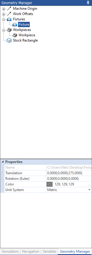
To adjust the workpiece or fixture you need to click on the added workpiece or fixture located under their heading in the Geometry Manager. The Properties table will then appear in the lower part of the Geometry Manager.
 |
|
Adjusting the Fixture and Workpiece. |
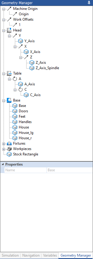
The following options are included in the Geometry Manager when the Machine Simulation add-on is being used.
 |
|
Geometry Manager tab – Machine Simulation. |
Shows head of machine and all additional axis that are applied. Right clicking this icon allows for machine parts to be added to open machine configurations and setting the visibility.
Shows the table of the machine and all additional axis that are applied. Right clicking this icon allows for machine parts to be added to open machine configurations and setting the visibility.
Shows the base of the machine and all additional axis that are applied. Right clicking this icon allows for machine parts to be added to open machine configurations and setting the visibility.
Identifies the axis that will have a linear movement during the machine simulation.
Identifies the axis that will have a rotary movement during the machine simulation.