The main configuration is entered most easily by selecting the icon ![]() Setup CNC-Calc from the File menu.
Setup CNC-Calc from the File menu.
 |
|
Opening the CNC-Calc setup window. |
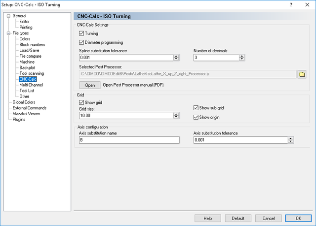
It is important to select first the correct machine type under the File types setup dialog, since all settings will apply for the selected machine. The window below shows the main configuration dialog.
 |
|
Main CNC-Calc configuration window. |
The top part of the CNC-Calc configuration dialog contains the settings for toolpath output, with the settings for the drawing grid at the bottom section.
Check this option to select turning (lathe) output.
Selects whether X axis output is in diameter measurement or in radius measurement. This option is only available if turning (lathe) output is selected.
This is the tolerance used when splines are substituted by line segments. The finer the tolerance the larger and more precise the programs will be.
This indicates the number of decimals that should be used when splines are substituted by line segments.
Use this field to specify the post processor that should be used to format the output of the CNC-Calc operations. Click the folder icon ![]() at the right of the field to browse for the desired post processor.
at the right of the field to browse for the desired post processor.
When this button is clicked the Post Processor Manual will be opened. This manual describes how to make the most common changes to a Post Processor. That could be things like how to change the output of G03 so they use radius (R) instead of center relative to start point (I,J and K).
If changes need to be made to a post processor to suit your personal needs, feel free to contact CIMCO A/S at info@cimco.com or at telephone +45 4585 6050.
Use this check box to specify if the grid should be shown.
Use this field to set the spacing between main grid points.
Select this option to have a sub-grid visible when zoomed in to a degree that shows few main grid points.
Select this option to have lines along X and Y zero visible.
Enter the axis name of the axis used in axis substitution. This is typically A if the axis rotates about the X-axis and B if it rotates about the Y-axis
This is the tolerance used to generate the axis substitution programs. The finer the tolerance the larger and more precise the programs will be.