The main configuration is entered most easily by selecting the icon ![]() Setup CNC-Calc from the File toolbar.
Setup CNC-Calc from the File toolbar.
 |
|
Opening the CNC-Calc setup window. |
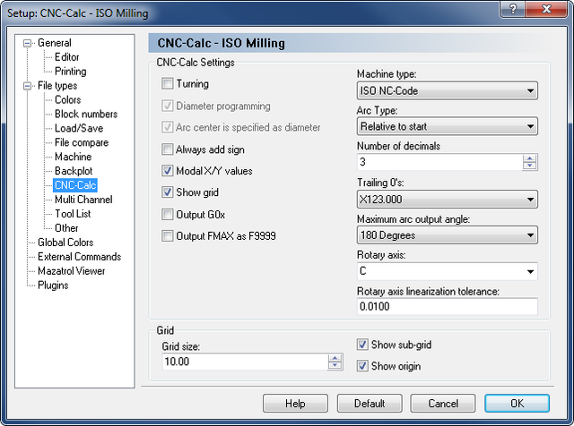
It is important to select the correct machine type, and it should be noted that the selection between ISO and Heidenhain conversational NC code output is made by the template used when creating the machine type. The window below shows the main configuration dialog.
 |
|
Main CNC-Calc configuration window. |
The top part of the CNC-Calc configuration dialog contains the settings for toolpath output, with the settings for the drawing grid at the bottom section. The correct settings for toolpath output depend on the machine and the control that is to run the NC code. If in doubt, you should consult the programming manual for your specific machine.
Select this for turning (lathe) output. This option is unavailable for Heidenhain conversational NC code output.
Selects whether X axis output is in diameter measurement or in radius measurement. This option is only available if turning (lathe) output is selected.
Selects whether the I value for arcs is specified in diameter measurement or in radius measurement. This option is only available if turning (lathe) output is selected.
Selects whether to always output the sign of the coordinate (giving a + sign on positive and zero coordinates), or whether the sign is only output on negative coordinates.
Selects whether the coordinates are modal or not. Modal coordinates means the coordinates are only output when changed, while non-modal coordinates means both X and Y are output on every line, regardless of whether they are changed or not.
Select this to make the grid visible.
Is used to format the ISO G-Code output format. With Output G0X disabled G01 will be formatted as G1.
This only affects Heidenhain machines. Here the Rapid moves are normally formatted as FMAX but with the field enabled the format will be F9999 that the older Heidenhain controllers use.
Select the machine that the output should be formatted for. For milling this could be Heidenhain or ISO milling.
All coordinates are rounded to this number of decimals, and if padding with trailing zeroes is selected below, coordinates are padded with trailing zeroes to this number of decimals.
This is primarily used in milling, and it allows the operator to control the maximum sweep of the arcs. Some controllers can not handle arcs with a sweep larger than 180 degrees, and here it is possible to ensure that these arcs will not be generated.
If Y-axis substitution is used, this field contains the address letter of the axis used in this substitution.
When axis substitution is used, all Y-axis movements are transformed to an axis rotation. To control the precision of this transformation, the entered linearization tolerance is used.
This sets the spacing between main grid points.
Select this to have a sub-grid visible when zoomed in to a degree that shows few main grid points.
Select this to have lines along X and Y zero visible.